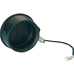
CE01 Drip-Proof Cap (for Receptacle / Adapter) (CE1RC-22RA)
Fare clic sull'immagine per ingrandirla.
Cliccare sull´immagine per ingrandirla.


- Sconto volumi elevati
Dettagli del prodotto:
Codice articolo del costruttore: CE1RC-22RA
Marca: MISUMI
Prezzo: 18.54 €
Tempi di consegna: 5 giorni
Dati Tecnici:
Compatible Shell Size: 22

● It protects the fitting portion and prevents the intrusion of dust and foreign matter. It also prevents accidents that are caused by the contact with live parts of the connector mating surface while it is not mated.
● It is IP55 when the cap is used.

· It is a dust-proof cap for the panel mount receptacle and relay adapter.
· The dust cap for plug has no string.
Codice componente
Qui sono indicati i codici componente
correlati al prodotto ricercato
CE1RC-22RA
Specifiche

| Model | Compatible Shell Size | Size (mm) | Weight (g) | |||
| ØA | ØB | ØC | L | |||
| CE1RC-18RA | 18 | 37.5 | 33.1 | 3.2 | 80 | 10.2 |
| CE1RC-20RA | 20 | 42.6 | 38.2 | 3.2 | 100 | 15.6 |
| CE1RC-22RA | 22 | 43.8 | 39.4 | 3.2 | 110 | 12.3 |
| CE1RC-24RA | 24 | 47.0 | 42.6 | 4.3 | 130 | 14.0 |
| CE1RC-28RA | 28 | 53.3 | 49.0 | 4.3 | 150 | 21.3 |
| CE01PC-18RA | 18 | 44.05 | 41.95 | - | - | 20 |
| CE01PC-20RA | 20 | 49.2 | 47.1 | - | - | 24 |
| CE01PC-22RA | 22 | 50.4 | 48.3 | - | - | 25 |
| CE01PC-24RA | 24 | 53.6 | 51.5 | - | - | 27 |
| CE01PC-28RA | 28 | 59.9 | 57.8 | - | - | 32 |
Più Informazioni

[ M ]Material / Finish
| Item | Panel Mounting / Relay | For Plug | ||
| Materials | Finish | Materials | Finish | |
| Body | EP Rubber | Black | EP Rubber | Black |
| String | Tetron | Black | — | — |
| Sleeve | Copper Alloy | Tin Plated | — | — |
| Crimp Terminal | Copper Alloy | Tin Plated | — | — |
Codice componente
|
|---|
| CE1RC-22RA |
| Codice componente |
Prezzo unitario standard
| Quantità minima d'ordine | Sconto volumi elevati | Compatible Shell Size | |
|---|---|---|---|---|---|
18.54 € | 1 | 5 giorni | 22 |
Loading...
Protection Circuit Connection Structural Diagram

About Compatible Products
NB01 connectors, CE01 connectors, and JL05 connectors are compatible with each other.Combination Method


Material / Finish
| Item | Materials | Finish |
|---|---|---|
| Shell (Body) | Aluminum Alloy | Black Chromate Treatment |
| Insulator | Polyester Resin | UL94V-0, Gray |
| Contact | Copper Alloy | Silver Plating |
| O-ring | Nitrile Rubber | Black |
| Coupling Nut | Aluminum Alloy | Black Chromate Treatment |
| Earth Lug | Steel Alloy | Silver Plating |
| Rear Gasket for Flange | Chloroprene Rubber | Black |
Electrical and Mechanical Properties, Compatible Wires
| Item | Characteristics | |||||||
|---|---|---|---|---|---|---|---|---|
| Rated Current | Contact Size | #20 | #16 | #12 | #8 | |||
| Maximum Value per 1 Piece | 5 A | 13 A | 23 A | 46 A | ||||
| Rated Voltage | Rating Classification | AC (r.m.s) | DC | |||||
| INST | 200 | 250 | ||||||
| A | 500 | 700 | ||||||
| D | 900 | 1,250 | ||||||
| Withstand Voltage | INST | 1,000 VAC (r.m.s) 1 minute | ||||||
| A | 2,000 VAC (r.m.s) 1 minute | |||||||
| D | 2,800 VAC (r.m.s) 1 minute | |||||||
| Insulation Resistance | 5,000 MΩ or more at 500 VDC | |||||||
| Contact Resistance | Contact Size | #20 | #16 | #12 | #8 | |||
| mΩ or less | 8 | 4 | 2 | 0.6 | ||||
| Operating Temperature Range | -55°C ~ +125°C | |||||||
| Waterproofing | IP67 Equivalent | |||||||
| Humidity | Relative Humidity 95% or less | |||||||
| Service Life | 500 Insertions and Removals | |||||||
| NB01 (Solder Type) Compatible Wires (Note 2) |
Contact Size | #16 | #12 | #8 | ||||
| Conductor Cross-sectional Area | 0.75 mm2 or less | 3.5 mm2 or less | 8 mm2 or less | |||||
| AWG Size | 18 or less | 12 or less | 8 or less | |||||
(Note 1) Rated voltage and voltage resistance are shown with rating classification symbols (INST, A; D). Refer as well to the table below.
Contact Arrangement Diagram
| Number of Contacts | 4 | 5 | 7 | 7 | 8 |
|---|---|---|---|---|---|
| Arrangement No. | 22-22 | 18-11 | 20-15 | 24-10 | 22-23 |
| Contact Size | #8 | #12 | #12 | #8 | #12 |
| Contact Arrangement (Note 1) (Note 2) |
 |
 |
 |
 |
 |
| Rating Classification | A | A | A | A | D (4), A (Others) |
| Number of Contacts | 10 | 17 | 19 | 19 | 24 |
|---|---|---|---|---|---|
| Arrangement No. | 18-1 | 20-29 | 18-19A | 22-14 | 24-28 |
| Contact Size | #16 | #16 | #20 | #16 | #16 |
| Contact Arrangement (Note 1) (Note 2) |
 |
 |
 |
 |
 |
| Rating Classification | A (3, 5, 6, 8), INST (Others) |
A | INST | A | INST |
| Number of Contacts | 30 | 37 | 52 | 73 |
| Arrangement No. | 20-30A | 28-21 | 24-52A | 28-73A |
| Contact Size | #20 | #16 | #20 | #20 |
| Contact Arrangement (Note 1) (Note 2) |
 |
 |
 |
 |
| Rating Classification | INST | A | INST | INST |
|---|
(Note 1) View from the male (pin) connector coupling surface.
(Note 2) The ○ in the arrangement table shows the earth terminals (for protection of terminal connections).
Panel Cut Size Drawing

| Compatible Shell Size |
φA ±0.5 |
φB +0.2 -0 |
C ±0.13 |
Mounting Screws (Reference) | Rear Mounting Panel Thickness Limit |
|
|---|---|---|---|---|---|---|
| Inch Screws | Metric Screws | |||||
| 18 | 30.2 | 3.3 | 26.97 | #4-40 | M3 | 3.0 or less |
| 20 | 34.9 | 3.3 | 29.36 | #4-40 | M3 | |
| 22 | 36.6 | 3.3 | 31.75 | #4-40 | M3 | |
| 24 | 39.7 | 4.3 | 34.92 | #6-32 | M4 | |
| 28 | 46.1 | 4.3 | 39.67 | #6-32 | M4 | |
Si trova sulla pagina di CE01 Drip-Proof Cap (for Receptacle / Adapter) , il codice articolo è il seguente: CE1RC-22RA.
Ulteriori dettagli concernenti specifiche e dimensioni si trovano sotto il codice prodotto CE1RC-22RA.
Configura
Proprietà di base
-
Compatible Shell Size
-
Filtrare per tipo dati CAD
- 2D
Filtrare per giorni di spedizione standard
-
- Tutti gli articoli
- 5 giorni o meno
Attributi opzionali
- Specifiche e dimensioni di alcuni componenti potrebbero non essere illustrate in modo esauriente. Per i dettagli esatti, consultare i cataloghi dei produttori .
Tipologia prodotto
| Codice componente |
|---|
| CE1RC-24RA |
| CE1RC-28RA |
| Codice componente | Prezzo unitario standard | Quantità minima d'ordine | Sconto volumi elevati | Giorni spedizione standard ? | Compatible Shell Size |
|---|---|---|---|---|---|
18.98 € | 1 | 5 giorni | 24 | ||
19.28 € | 1 | 5 giorni | 28 |
Supporto tecnico
Metodo di pagamento


Produzione on demand
Certificati


Copyright © MISUMI Corporation All Rights Reserved.